CNC File Formats: How to Prepare Files for Machining
Mirrored panels, hole patterns sitting 2 mm off and internal radii no cutter can reach are all invisible in a render. Some of them surface in CAM, some only at assembly, and all of them are cheaper to catch before programming starts.
That is why the file matters more than most design teams expect. A machine can only produce what the file communicates, and a drawing that looks correct on screen can still be unsuitable for production. This guide covers both halves of the question: which format to send for which operation, and what has to be true inside that file before it can be machined.
It is written for the work we actually receive at Cutlab: custom furniture, fitted interiors, retail fixtures and architectural components, cut from plywood, MDF, laminated board, solid wood and technical plastics.
Start with the operation, not the format
Before choosing a format, define what the machine has to do.
For cutting, drilling, pocketing and engraving on flat sheet, a 2D vector drawing is usually enough. For shaped surfaces and compound curves, a 3D model is normally required. For features on more than one face, send either a model or clearly coordinated drawings that identify each face and each feature depth. We machine on three axes, so features on several faces need separate setups and tool access has to be checked.
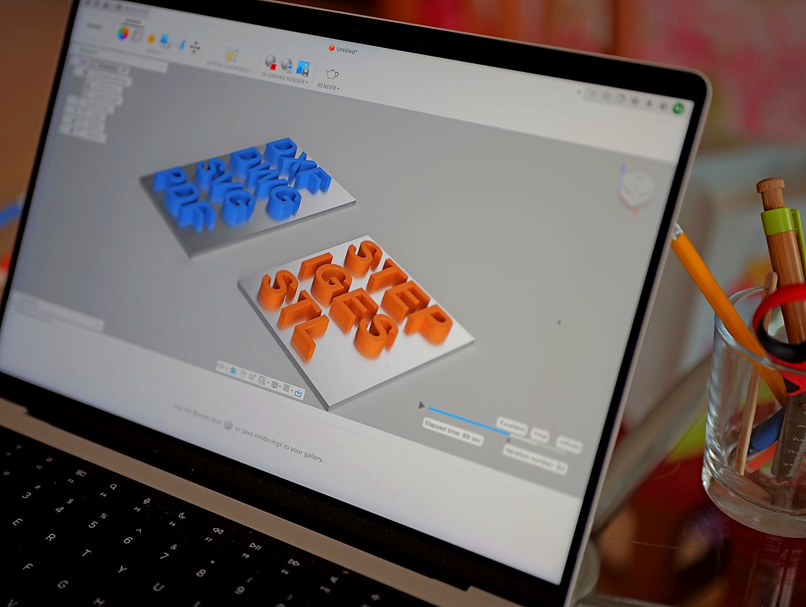
This is where most confusion starts. A PDF can show a cabinet side panel perfectly and contain no reliable geometry at all. A STEP model can carry excellent 3D data and say nothing about which face receives the visible finish. Neither file is wrong. Each is simply answering a different question from the one production needs answered.
The geometry is the centre of the package, but it is not the whole package.
2D formats for cutting and engraving
DXF: the reliable workshop standard
DXF is the most useful format for 2D CNC work. It is widely supported by CAD and CAM software and works well for sheet materials: plywood, MDF, melamine-faced board, HPL, acrylic and technical plastics.
A well-prepared DXF contains closed vector contours at full scale, normally in millimetres. It can also carry circles for drilling, lines for engraving, and separate layers for separate operations. That structure is what makes efficient nesting and sensible tool assignment possible.
DXF still needs a quality check before it reaches the machine. Duplicate geometry can produce repeated toolpaths or selection errors. Gaps of a fraction of a millimetre can stop a contour being recognised as closed. Exploded dimensions and unscaled imports create work; splines are fine in themselves, but check how they export and how our CAM software reads them before relying on them for a critical profile. Keep machining geometry clear and leave presentation elements out.
DWG: useful, but check what came with it
DWG is AutoCAD's native format and common in architecture and interior design. It can hold the same 2D information as DXF, including layers, dimensions, blocks and notes.
When sending DWG, remove what is not needed for fabrication: layouts, title blocks, presentation elements. Remove unused external references, but bind or package any reference that actually carries geometry we need. Keep the machining geometry on clearly named layers and state whether the drawing is in millimetres or inches. A clean DWG cuts preparation time.
SVG, AI and EPS: for graphic engraving
These are the right formats for logos, lettering, decorative patterns and perforated screens. They suit routed signage and branded panels well.
Two conditions matter. The file must contain true vector paths, not a placed raster image. And text must be converted to outlines. Expand strokes only where their width defines the area to be machined; keep centreline paths as they are for line engraving. A thin line on screen does not tell the machine whether to engrave, V-carve or cut through. That intent has to be stated separately, together with depth.
Please confirm compatibility with us before sending native CAD, AI or EPS files, so we can check them against our CAM software first.
PDF: reference, rarely production
PDF is valuable for communicating dimensions, elevations and approval layouts. It is not a dependable machining file. Some PDFs hold editable vector paths; others are flattened images, scans, or exports with fragmented geometry, and you cannot tell which from the outside.
Send the PDF. It communicates dimensions, layout and production notes better than anything else. Just pair it with DXF, DWG, SVG or a native CAD file when parts are actually being cut.
3D formats for milling and shaped parts
STEP: the preferred exchange format
STEP, as `.step` or `.stp`, is the strongest general-purpose format for 3D CNC work. It transfers accurate solid geometry between CAD platforms and handles furniture components, curved panels, joinery details and custom fixtures well.
It earns its place when a part has shaped edges, recessed hardware positions or genuine three-dimensional surfaces. It gives the CAM programmer a solid model to build toolpaths against; collision checking also depends on correctly defined tools, stock, fixtures and machine setup, which are ours to get right.
For assemblies, include individual part files and an assembly model where both exist. Individual parts are easier to program and nest; the assembly is what confirms how they relate. Sending both is not excessive.
IGES: for surface models
IGES (`.igs`, `.iges`) is older but still appears for complex curved forms from industrial design or specialist 3D software. Its limitation is that it can contain surfaces which are not joined into a watertight solid. That does not make it unusable, but it may need repair before programming.
If both STEP and IGES exist, send STEP.
STL: mesh geometry
STL describes a form as a triangle mesh. It suits 3D printing and works for milling sculptural or organic surfaces, but it approximates surfaces with triangles and does not carry editable features, exact curves or hole definitions. It also does not state its units reliably, so tell us the export units and we will check a known dimension after import.
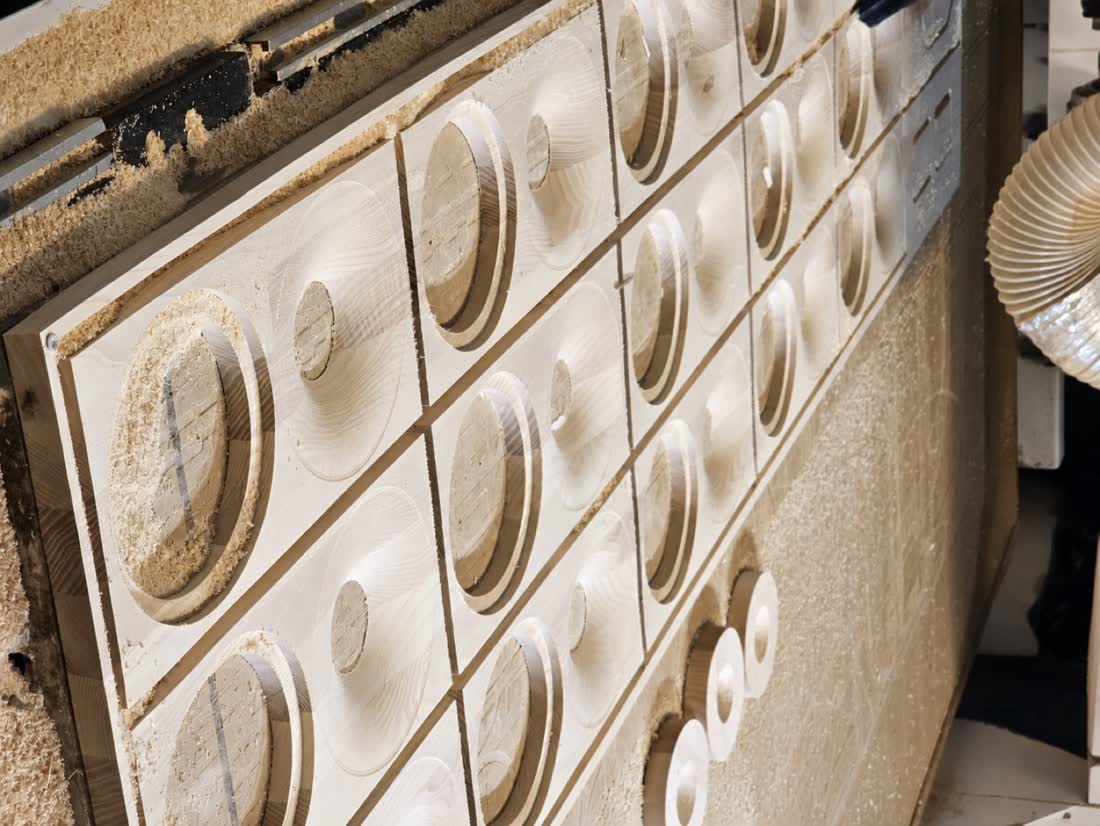
Use it for a relief pattern or a freeform surface, with mesh resolution matched to the surface accuracy you need. For furniture components and construction details with precise dimensions, send the native model or STEP instead.
Native CAD files
Files from SolidWorks, Rhino, SketchUp, Fusion or AutoCAD are useful alongside an exchange format. They preserve design information and give production options if a conversion issue appears.
They do not replace a fabrication package. A SketchUp model may communicate an interior beautifully and lack accurate joinery, board thicknesses or manufacturable part geometry. A Rhino model may have excellent surfaces that need checking for open edges. A format is only as production-ready as the model inside it.
G-code: we make it ourselves
G-code contains the machine instructions: movement, feed rates, spindle speed, tool changes, paths. It is not normally something a client should supply.
G-code is machine-specific. A program written for one router can be inaccurate or unsafe on another, because workholding, tool library, post-processor, machine limits and zero point all differ. We treat CAM preparation as part of production control rather than a conversion step, because the machining strategy has to suit the material, the finish requirement and the consistency needed across the run.
What makes a file production-ready
Format is the easy part. These are the conditions that decide whether a file moves straight to programming or comes back with questions.
Everything at 1:1, units stated. A file exported in inches and assumed to be millimetres means rescaling and rechecking the whole package. State the unit even when it seems obvious.
Closed contours for part outlines and cut-outs. A contour that looks closed on screen can fail during toolpath generation, or produce an incomplete cut. Open paths are legitimate for some cuts, so identify any that are intentional.
No duplicate or stray geometry. Overlapping lines get machined twice. Stray entities parked off the sheet interfere with nesting and usually mean the file was never cleaned.
Layers that separate operations. Cut-through, pocket, drill, engrave, reference. A circle on an unnamed layer might be a through-hole, a shallow pocket or a drill point, and someone has to stop and ask.
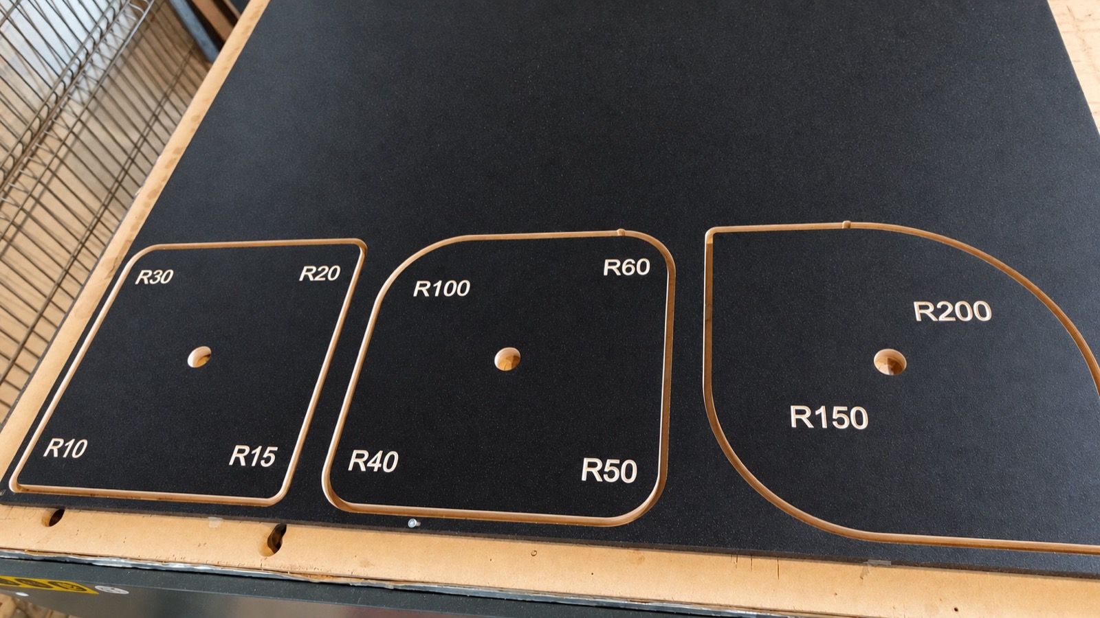
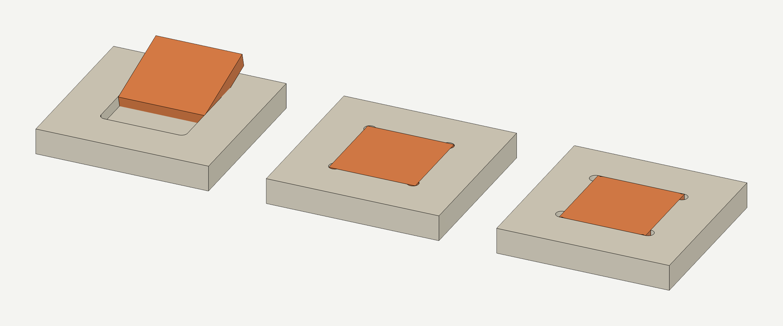
Geometry drawn for a round tool. An internal corner in a routed profile keeps the cutter radius. Where a square-edged part has to seat into it, agree a corner relief such as dog-bone or T-bone, a revised mating shape, or secondary finishing. Very narrow strips, fragile internal details and small unsupported pieces need a different strategy, and it is cheaper to decide that in CAD.
Left- and right-hand parts clearly identified. Mirrored components are a specific risk in fitted interiors, where one wrong orientation disrupts assembly on site rather than in the workshop.
What the file cannot tell us
Geometry alone does not reliably communicate the things that determine the result:
Put these in an annotated drawing or a short specification alongside the geometry. It is the cheapest thing a design team can add to a package.
Why clean files cost less
Most production problems are cheaper to solve in the file than on the workshop floor. That is the economic case, and it is not abstract.
Rework. If internal corners are square but the parts must slot together, someone decides whether to add reliefs, change the joint or redesign neighbouring components. Decided early, the project stays efficient. Decided after machining, it means recutting parts and hand-finishing the ones already made.
Material yield. When parts arrive with correct orientation, grain direction and sensible spacing, sheet usage improves. On custom furniture and interiors, material is a large enough share of the quote that a better nest can reduce the price.
Quoting speed. A workshop quotes faster and more accurately when files are organised, dimensions are final and material assumptions are clear. On fit-out schedules tied to launch dates and installation slots, a delay caused by a preventable file issue is rarely contained to one party.
File preparation and finish quality
CAD/CAM is usually treated as a cutting question. It is also a finishing question.
Tool choice, feed strategy and cutting direction influence breakout and edge sharpness, and they matter most on the materials where they show: veneered board, melamine-faced panels, anything with a visible edge. If the file does not separate operations or identify visible faces, parts arrive technically cut and still needing preparation before finishing.
The same applies to engraving and 3D milling, where depth control, geometry quality, toolpath spacing, tooling and material all affect the visual result. Finishing is worth thinking about while the file is still being prepared.
If you do not have a proper file yet
That is normal, and it is not a problem.
Some clients send DXF or STEP that needs only checking and optimisation. Others start with a sketch, a PDF layout, a moodboard or a photograph, and the manufacturing logic has to be built around the idea: construction details, board thicknesses, assembly method, edge conditions, finishing.
Send the clearest version of what you have rather than forcing an uncertain export. A rough sketch with a clear intention is more useful than a CAD file that quietly disagrees with itself.
CNC machining is 60 €/hour with program preparation included. Where a drawing has to be created or reworked first, CAD design is 75 €/hour. Minimum order 100 €. VAT is added. Involving the workshop early can avoid later revisions.
Checklist before you send
For most 2D sheet work, a clean DXF plus a dimensioned PDF is a practical combination. For 3D milling, STEP plus reference drawings. For graphics, SVG, AI or EPS with the engraving intent written down.
A clear, complete package is what lets the workshop move forward without stopping to guess.
22.09.2026